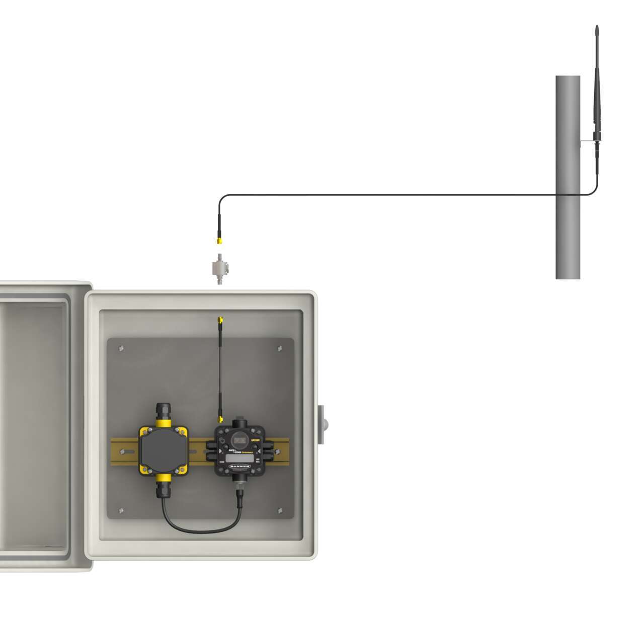
Antenna Performance
30 September 2010
Introduction
In this new age of wireless technology, controls and automation engineers are increasingly asked to evaluate and install wireless sensing and monitoring systems into a wide range of environments. To take advantage of the flexibility, reliability, and ease of installation that wireless networks offer, engineers must familiarize themselves with new technology and new terminology, especially related to the antennas used in wireless systems.
The antenna is an important component of a wireless network. The proper antenna can optimize the range and reliability of a radio network while the wrong antenna causes high performance wireless devices to appear to stop operating.
This white paper will give controls and automation engineers the basic knowledge of key performance characteristics used to analyze antenna performance within the installation environments. These metrics include an understanding of:
- Antenna performance
- Gain
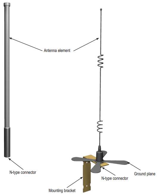
- Antenna types
- Line of sight
- Link margin calculations
Anatomy of an Antenna
What Do Antennas Do?
Antennas transmit radio signals by converting radio frequency electrical currents into electromagnetic waves. Antennas receive the signals by converting the electromagnetic waves back into radio frequency electrical currents.
Because electromagnetic waves do not require a medium in which to travel, antennas can function in air, space, under water or other liquid, and even through solid matter for limited distances. Every antenna has specific characteristics that determine the signal’s range and radiation pattern or shape. One of the most important characteristics of the antenna is its gain.
Gain
The shaping of the radio signal is what is referred to as antenna gain. Similar to how nozzles redirect the flow of water, antenna gain focuses the radio signal in a particular direction and radiation pattern. The higher the gain of an antenna, the more focused the signal.
Antenna gain is measured in decibels. A decibel is a logarithmic ratio between a specific value and a base value of the same unit of measure. With respect to radio power, dBm is a ratio of power relative to 1 milliwatt, where 1 mW equals 0 dBm.
The first table shows the logarithmic relationship between dBm and power: a small change in dBm results in a large change in power.
For every reduction of 10 dBm the power is reduced by a factor of ten and power levels below 1 mW are negative decibels. The second table illustrates how the system’s power is reduced by half with a change of only 3 dBm.
Experimentation indicates that for every 6 dB increase in gain, the radio signal range doubles. Therefore, if a radio system with a unity gain antenna (0 dB gain) transmits two miles, a 6 dB antenna on the same radio transmits the signal four miles.
Specifications for most antennas refer to the gain in either dBm, dBi, or dBd. While it isn’t important to understand at this point what these decibel ratings refer to, a good rule is:
dBm = dBi = dBd + 2.15
When adding the gains and losses of a total radio system, always use the same dB unit for each system component.
In addition to increasing the range, adding gain changes the radiation pattern. How the radiation pattern changes depends on the type of antenna: omni-directional or directional.
| dBm | Power |
|---|---|
| +20 | 100 mW |
| +10 | 10 mW |
| 0 | 1 mW |
| -10 | 100 µW |
| -20 | 10 µW |
| -30 | 1 µW |
| -40 | 100 nW |
| -50 | 10 nW |
| -60 | 1 nW |
| -70 | 100 pW |
| dBm | Power |
|---|---|
| 30 | 1.00 W |
| 29 | 794 mW |
| 28 | 631 mW |
| 27 | 501 mW |
| 26 | 398 mW |
| 25 | 316 mW |
| 24 | 251 mW |
Omni-Directional Antennas
As the name implies, an omni-directional antenna transmits and receives radio signals equally in all directions. Because of the physics associated with radio, an omni-directional antenna’s effective signal pattern looks like a doughnut with the antenna located in the center of the doughnut hole. A good example of an omni-directional antenna is a radio station transmission tower mounted on a mountaintop. Antennas used on cell phones or walkie-talkies are also omni-directional antennas.
In a wireless network, omni-directional antennas are best suited to indoor environments and for devices at the center of a star topology network. For long range point-to-point communications, omni-directional antennas would not be the best option.
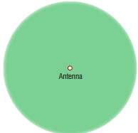 The top view of an omni-directional antenna appears to extend evenly in all directions
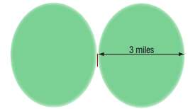 Viewed from the side, however, omni-directional antennas have more of a doughnut pattern.
Note the lack of a signal very close to the antenna. Most dipole omni antennas have a minimum distance for optimum signal reception.
High Gain
An omni antenna with increased gain also has a circular radiation pattern when viewed from the top. From the side view, however, the decreased energy sent vertically increases the energy transmitted horizontally. The radiation pattern stretches to extend the range, focusing the signal along a horizontal plane.
This makes high gain omni antennas more sensitive to changes in elevation between the two radios.
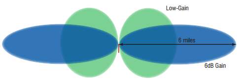 Increasing the gain of omni-directional antennas results in less energy sent vertically and more energy sent horizontally, extending the range.
Directional (Yagi) Antennas
A Yagi antenna, named after its inventor, is a directional antenna because it focuses most of the energy of the transmitter or receiver in a single direction. If you compare antenna radiation patterns to light, an omni antenna radiates a radio signal like a light bulb — evenly in a spherical pattern. A directional antenna radiates similar to a flashlight — focusing the signal only in one direction. The higher the gain, the more focused the beam becomes.
Yagi antennas are ideally suited for long range, line-of-sight communications. In sensor networks, Yagis are often used in outdoor applications like tank level monitoring. If there is no line of sight, a Yagi antenna will not perform well.
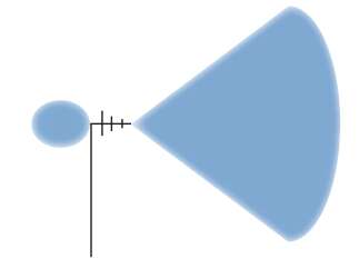 A Yagi antenna radiates a signal in one direction.
High-Gain Yagis
Because Yagi antennas yield narrower radiation patterns, accurately aiming a high-gain Yagi is important when setting up a radio network. Radio network installers can use a variety of tools to accurately aim a Yagi including scopes, laser sights, and trial and error.
The higher the gain of the antenna, the more the signal is focused along a specific plane. High-gain antennas should only be used for line-of-sight applications.
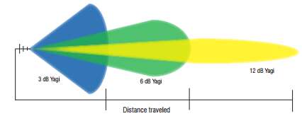 As the Yagi’s gain increases, the radio signal becomes more focused along a specific path.
The Importance of Line of Sight
Accurate radio transmission depends on a clear path between radio antennas known as the line of sight. If any obstructions, including buildings, trees, or terrain, interrupt the visual path between antennas, the obstructions will also interfere with the radio signal transmission, resulting in multi-path fade or increased signal attenuation.
Multi-path fade is the result of radio signals reaching the receiver via two or more paths. In industrial settings, a received signal may include the line of sight signal in addition to signals reflected off buildings, equipment, trees, or outdoor terrain. Signal attenuation is the decrease in signal strength as a result of travel through the medium, in this case the air.
 Line of sight may be preserved, but obstructions in the first lobe of the Fresnel zone may still cause reception problems.
Despite a clear line of sight, obstructions in the Fresnel zone, a three-dimensional ellipsoid formed with the two antennas as the foci, will still interfere with the radio signal and cause multi-path fade. Raise the antennas high enough to clear any obstructions. Ideally there should be no obstructions anywhere in the Fresnel zone, even if line-of-sight is preserved.
If a radio network site is spread over a large area with multiple obstructions or a variety of terrain, conduct a site survey to determine optimum antenna locations, antenna mounting heights, and recommended gains for reliable performance.
Radio Power and the FCC
When reviewing data sheets for radio products, two important specifications to notice are the transmit power and receive sensitivity of the radios.
The transmit power represents transmitted signal strength while the receive sensitivity refers to the minimum signal strength the receiver can reliably detect. Both specifications are specific to the radio, not the antenna, and are given in dBm or in milliwatts.
For the transmitter, larger positive numbers indicate strong transmission. For the receiver, smaller numbers indicate better reception (receiver sensitivity is always a negative number). Even a 1 dBm shift in transmit power or receive sensitivity can represent a significant difference in radio range.
According to rules established by the FCC, radio systems operating in the unlicensed bands are restricted in the power of their radio systems. No radio system may exceed 30 dBm total radiated power, or approximately 1 Watt.
Link Margin Calculations
When two radios are communicating they are said to be linked. The quality or strength of the link is measured in decibels (dB). The “link margin equation” is the main tool engineers use when determining how far a radio signal travels. According to radio theory, any link margin greater than 0 dB is a strong link. In practice, systems engineers feel comfortable when the link margin between two radios is at least 6 dB, and preferably 10 dB.
Link margin is calculated using the following equations:
- Link Margin = (Total System Loss) – (Receiver sensitivity)
- Total System Loss = Transmitter gain + receiver gain + free space loss
The total system loss is a negative number because the total gains of the transmitter and receiver are positive numbers and the total free space loss is a negative number. The receiver sensitivity is a negative number.
If the resulting link margin is greater than 10 dBi, the receiver should reliably receive the radio signal. If the resulting link margin is less than 10 dBi, the antenna used for the calculations may not be the correct antenna for this environment. If the FCC regulations have not been exceeded, consider using an antenna with a higher gain and recalculate the link margin.
Free Space Loss
Free-space loss refers to the part of the radio signal that naturally degrades as it travels through the atmosphere and is unrelated to the antenna type or its specifications.
Radio signal range is inversely proportional to frequency. The lower the frequency, the longer the range and the less susceptible the signal is to path-loss and interference. The equations for free space loss are:
FSL900MHz = 31.5 + 20 Log d (where d is in meters)
FSL2.4GHz = 40 + 20 Log d (where d is in meters)
Putting It All Together
When calculating the total gain of a transmitter or receiver, include all losses from cabling, connectors, any item contributing to the signal propagation.
Data sheets for all radio transmitters, receivers, antennas, cabling, and connectors should list the transmit power, receive sensitivity, antenna gain, and cabling losses. Connector pairs may have a 0.5 dB loss while a lightning arrestor could include a loss of 0.5 to 1.5 dB. Cabling losses vary by manufacturer and are typically listed per 100 feet of cable.
The only parameter in question is free space loss. Using the equation for free space loss, systems engineers should be able to determine if there is sufficient link margin for each link in a point-to-point radio system.
Banner's Sure Cross System
| Basic Specifications | Example Applications | |
|---|---|---|
| Omni-Directional | Transmit and receive equally in all directions. Ideally suited for the center device in a star topology network. With higher gain, transmit less signal vertically and more signal horizontally in all directions. |
Low-gain omni antennas work well in any multipath or industrial environment such as monitoring and signaling bins for parts picking, monitoring automotive manufacturing steps, or regulating environmental conditions such as temperature and humidity. |
| Directional | Transmit and receive best in a single direction. Requires a clear line-of-sight between devices. With high gain, transmit less signal vertically and more signal horizontally in one direction. |
Yagis are best suited to long range, line-of-sight applications such as monitoring tank farms, waste water, or large-scale agricultural production facilities. |
Once an antenna is installed, analyzing the signal strength is easy with Banner’s Site Survey feature included with all Gateway devices. Conducting a Site Survey analyzes the radio communications link between the Gateway and any Node within the network by reporting the number of missed and received data packets. Site Survey results are listed as a percentage of data packets received and indicate the signal strength of the received signal.
Monitoring and control in processing applications are limited only by imagination. From tank levels to line pressure, from temperature to voltage, the Sure Cross Wireless Network can be easily and reliably deployed, scaled, analyzed, and redeployed into most environments.
