All Agriculture Solutions
-
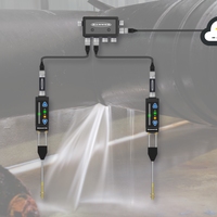
Monitor Leaks in Your Critical Applications
Monitor Leaks in Your Critical Applications
Monitor leaks in your critical applications and receive real time alerts when they occur.
-
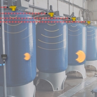
Bring In IO-link Sensor Data for Tank Level Applications Wirelessly
Bring In IO-link Sensor Data for Tank Level Applications Wirelessly
Wirelessly integrate IO-link sensor data for tank level monitoring with Banner's DXM controllers and T30R sensors for accurate, remote data analysis.
-
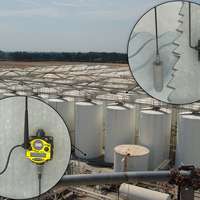
Wireless Tank Farm Monitoring in Unsafe or Harsh Conditions
Wireless Tank Farm Monitoring in Unsafe or Harsh Conditions
With a SureCross Wireless Network, FlexPower Nodes are deployed at each tank without the need to run cables for power or I/O data transmission. Banner’s unique power management capability enables a Node equipped with a pressure sensor to operate for years on a single DX81 battery power supply.
-

Fill Level of Dry Material in a Hopper
Fill Level of Dry Material in a Hopper
An L-GAGE LT3 laser distance-gauging sensor, mounted above the hopper, measures the distance to the material's irregular surface, enabling a PLC to calculate the bin’s fill level.
-
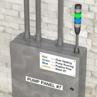
Indicating Pump Panel Status
Indicating Pump Panel Status
Banner's tower lighting solutions, such as an EZ-LIGHT TL50 Tower Light, can be mounted on top of the pump panel to easily communicate the status of the pump. The highly visible light tower allows employees to quickly check the panel, without needing to open the panel door. Multiple lights can be on simultaneously, so several messages can be conveyed at once, and the audible alert provides indication that the pump is overheating and immediate attention is required.
-

Log Measurement
Log Measurement
In this application, an EZ-ARRAY measuring light screen is being used to measure the length of the log. The EZ-ARRAY determines the total number of beams that are blocked by the log and communicates the length of the log to an operator station by sending the information to the system controller in the form of a MODBUS RTU-485 output. The operator station controller then provides a number of options to the operator, who selects which cuts are made.
-
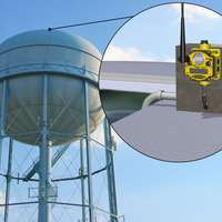
Water Tower Level Monitoring and Pump Control
Water Tower Level Monitoring and Pump Control
A submersible pressure sensor and float switches connected to a FlexPower™ Node provide constant monitoring of water tower levels and wirelessly transmits data to a Gateway mounted near the pumps.
-
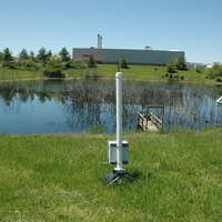
Monitoring Retention Pond Levels
Monitoring Retention Pond Levels
Large facilities may have several runoff ponds in widely distributed locations. Using a wireless monitoring system eliminates the need for someone to drive out to each pond to monitor water levels.
-
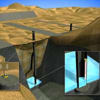
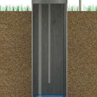
Waste Water Management in a Land-fill Site
Waste Water Management in a Land-fill Site
After careful consideration of several systems, the operators of the landfill determined that the Banner Wireless system was the only solution that could meet all imposed standards and seamlessly co-exist with other devices already in place at their site. With the help of integrator Wilson Mohr, they were able to create a system that could take data from below ground and make it accessible at the desk of the end user. One battery powered Node at the top of each well powers the radio and the ultrasonic analog level sensor. Each Node is equipped with a specialized low-power 4-20 mA analog level sensor and one 10-30V dc powered Gateway controls the system. The Data Radio and Modbus master controller module enhance portability of data and an omni-directional antenna extends the range of Gateway-Node communication up and over the hill and across the landfill site. Cutting-edge power management capabilities and an internal battery eliminate long haul cabling and create a greatly-reduced cost of installation. The wireless devices also have built-in diagnostic properties that send out alarms prior to complete shutdown, minimizing down time. They are also completely scalable and can adapt as the operators fill in and create new wells.
-

Tank Level Monitoring
Tank Level Monitoring
Using K50U ultrasonic sensors and Q45U wireless nodes paired to a DXM100 wireless controller, we can develop a wireless monitoring system for multiple tank level measurements that is easy to set up, interpret the results, and monitor locally through a cloud-based system.
-

High-Speed Soybean Counting
High-Speed Soybean Counting
Banner Engineering has paired the technology of the D10D Expert with fiber optic arrays optimized for small object counting to create the D10 Expert Small Object Counter.
-
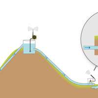
Gravity Irrigation with Pump and Flow Control
Gravity Irrigation with Pump and Flow Control
The Gateway, or wireless network controller, monitors the water level inside the water tank. When the water level drops, a Node installed with the reservoir pumps uses its outputs to cycle the pumps on or off. A series of Nodes monitors the amount of water flowing into each orchard. A 1 Watt Data Radio connected to the Gateway transmits the data to a mobile asset or a centralized control center for data processing and billing.
-
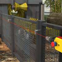
Outdoor Log Debarking
Outdoor Log Debarking
In the event of a problem or potential equipment damage, anyone along the length of the rope pull cable (up to 75 meters) can pull the cable or press the built-in E-stop button and stop the operation of the machine. The switch is ruggedly built, to allow for outdoor mounting even in inclement conditions. It provides visible rope tension indication and an auxiliary output for remote tension monitoring.
-
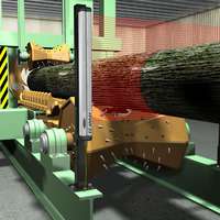
Debarking Control
Debarking Control
As a log moves toward the debarker, an EZ‑ARRAY receiver determines the total number of beams that are blocked. It sends an analog signal to the debarking station logic controller, which determines the diameter of the log and adjusts the log grippers and debarking blades to the log’s size. Accurately determining the log's size provides process stability and prevents damage to the debarking machine.
-
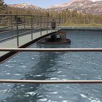
Automating Data Collection for On-Site Water Treatment
Automating Data Collection for On-Site Water Treatment
Using Banner's wireless sensors, one company was able to focus on other outstanding maintenance issues and still reliably collect the water level data needed to comply with standard water treatment practices.
-

Controlling Pivot Irrigation
Controlling Pivot Irrigation
A municipality has over 30 farm fields irrigated with gray water using pivot irrigation systems. Local regulations prohibit the irrigation system from spraying over roads and ditches. The customer needs a solution that can reliably control the water flow to the end nozzle based on predetermined location coordinates.
-

Collecting Snap Samples
Collecting Snap Samples
To collect snap samples quicker and avoid exposure to wastewater, use wireless technology to automatically collect snap samples and deliver the contents to the collection jug. A small pump installed at the collection site can be activated automatically, and at programmed time intervals, to extract the snap sample. A wireless signal is used to trigger the collection and to confirm a successful collection.
-
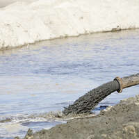
Detecting Leaks Along a Coal Slurry Pipeline
Detecting Leaks Along a Coal Slurry Pipeline
While the slurry is pumped from the mine site over hills into the retention pond, the flow rates are measured at the origination site and at the retention pond.
-
Landfill Leachate Pump Cycle Counting
Landfill Leachate Pump Cycle Counting
Leachate removal from a landfill well is a primary function to guarantee consistent landfill gas production. Instead of manually collecting the pump count data, wireless technology can be used to save time and eliminate errors.