QM30VT3 3-Axis Vibration Sensor Overview
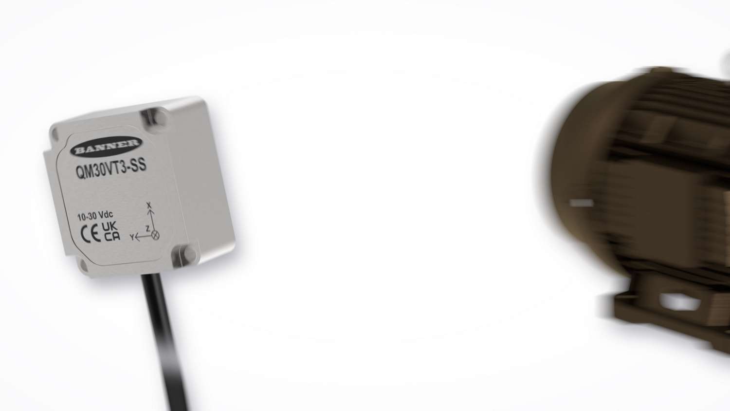
An overview of the QM30VT3 3-Axis Vibration Sensor's functionality
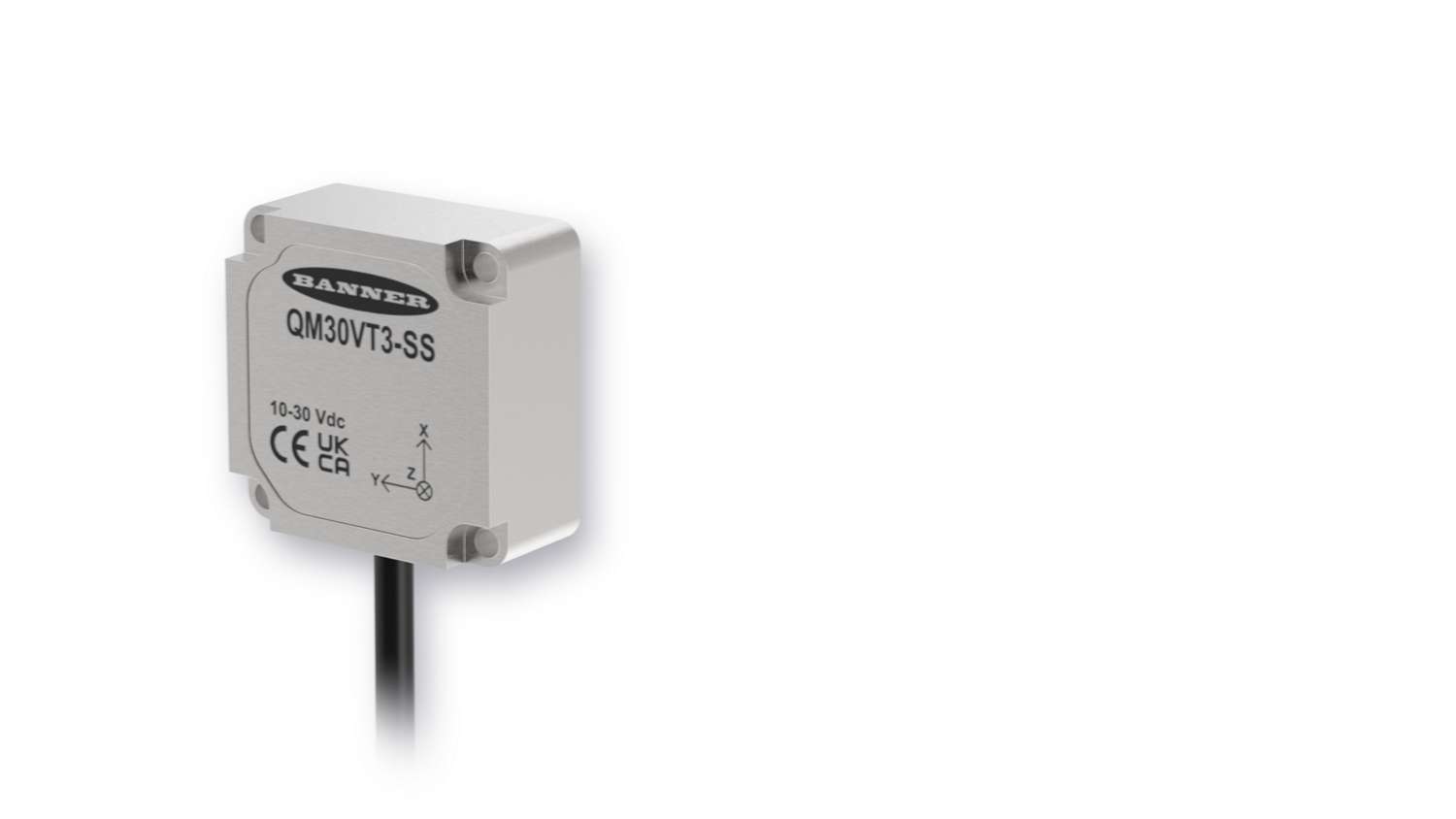
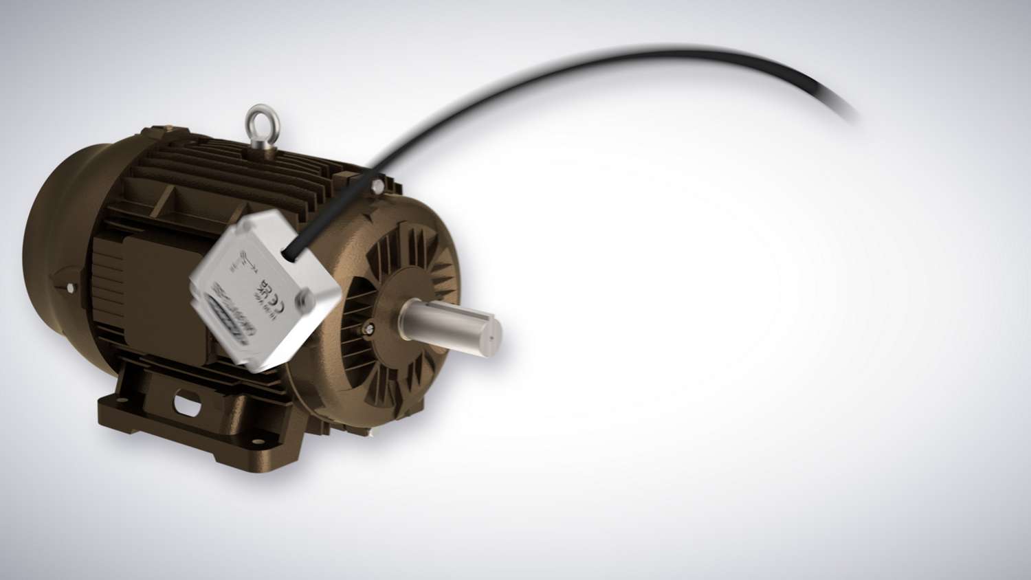
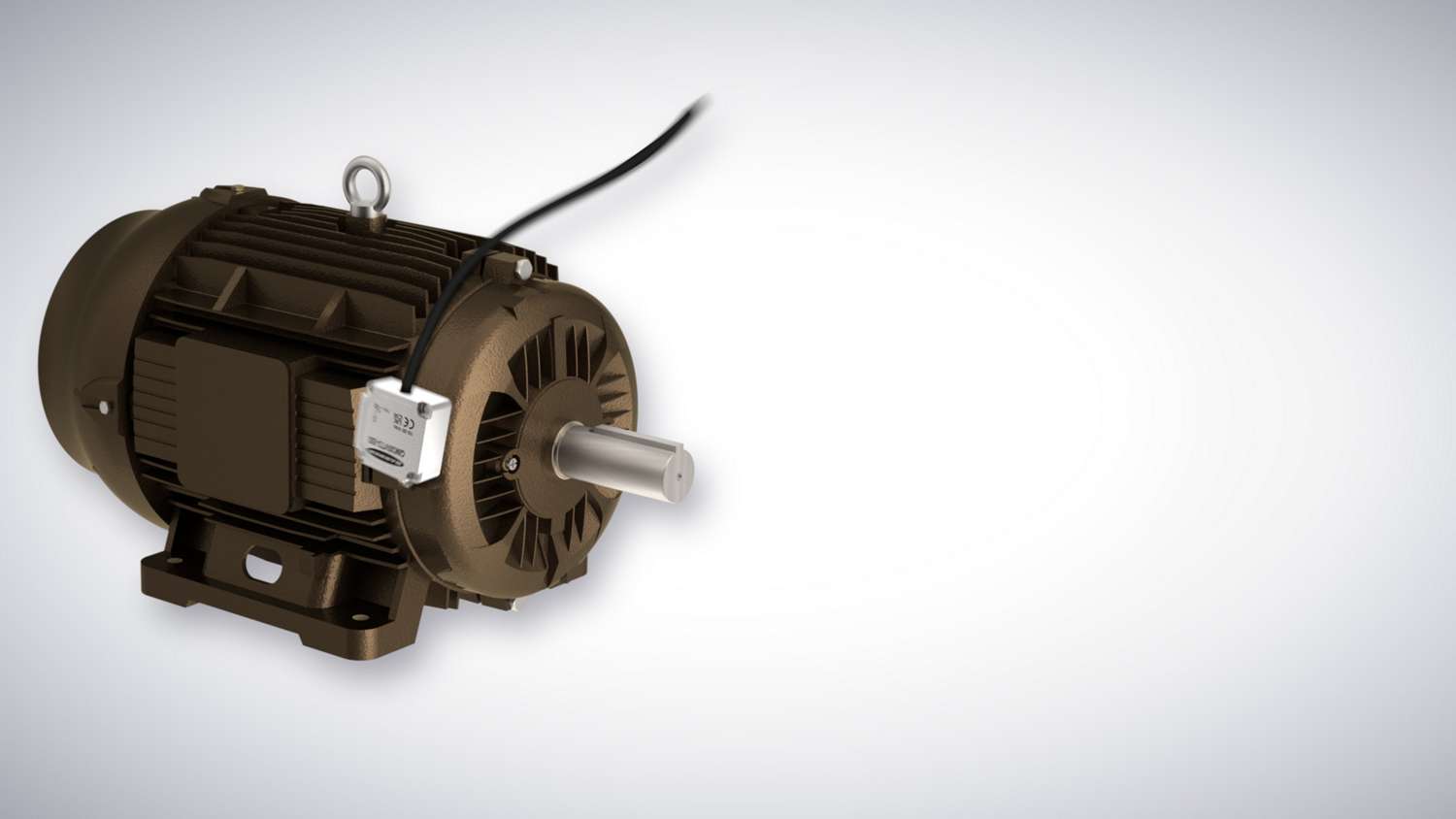
The QM30VT3 High-Performance 3-Axis Vibration Sensor helps catch failures earlier, reduce downtime, and simplify predictive maintenance with precise, real-time diagnostics so teams can act before problems escalate. Built-in VIBE-IQ machine learning automatically establishes baseline levels and alert thresholds, delivering real-time fault detection without complex configuration while eliminating the need for external gateway or controller processing. By processing data on the sensor itself, the QM30VT3 simplifies integration into Modbus networks. High-resolution 3-axis sensing captures more faults across all three axes, while advanced signal processing ensures early detection of developing mechanical issues—helping teams prevent unexpected breakdowns and costly repairs.
QM30VT3 3-Axis Vibration Sensor
Sensing
Built-in
Faster Sampling and Processing than the VT2
is Configurable
Vibration Analysis
Ultra-low noise vibration monitoring on all three axes—X, Y, and Z—ensures a more complete view of machine health and greater installation flexibility compared to 2-axis sensors and most 3-axis MEMS sensors, which have up to three times more noise on their third axis. The QM30VT3 delivers ultra-low noise performance across all three axes, capturing vibration patterns that indicate critical early-stage faults that others miss, including angular misalignment and dynamic imbalance. Documenting which of the sensor’s axes correspond to the machine’s axes, the sensor can be mounted in the orientation that best fits the application, detecting everything from subtle imbalance to early-stage bearing wear—regardless of orientation or mounting position.
With VIBE-IQ built into the sensor, machine learning detects vibration baselines and automatically generates warning and alarm thresholds so anyone can monitor assets—no gateway or expertise required.
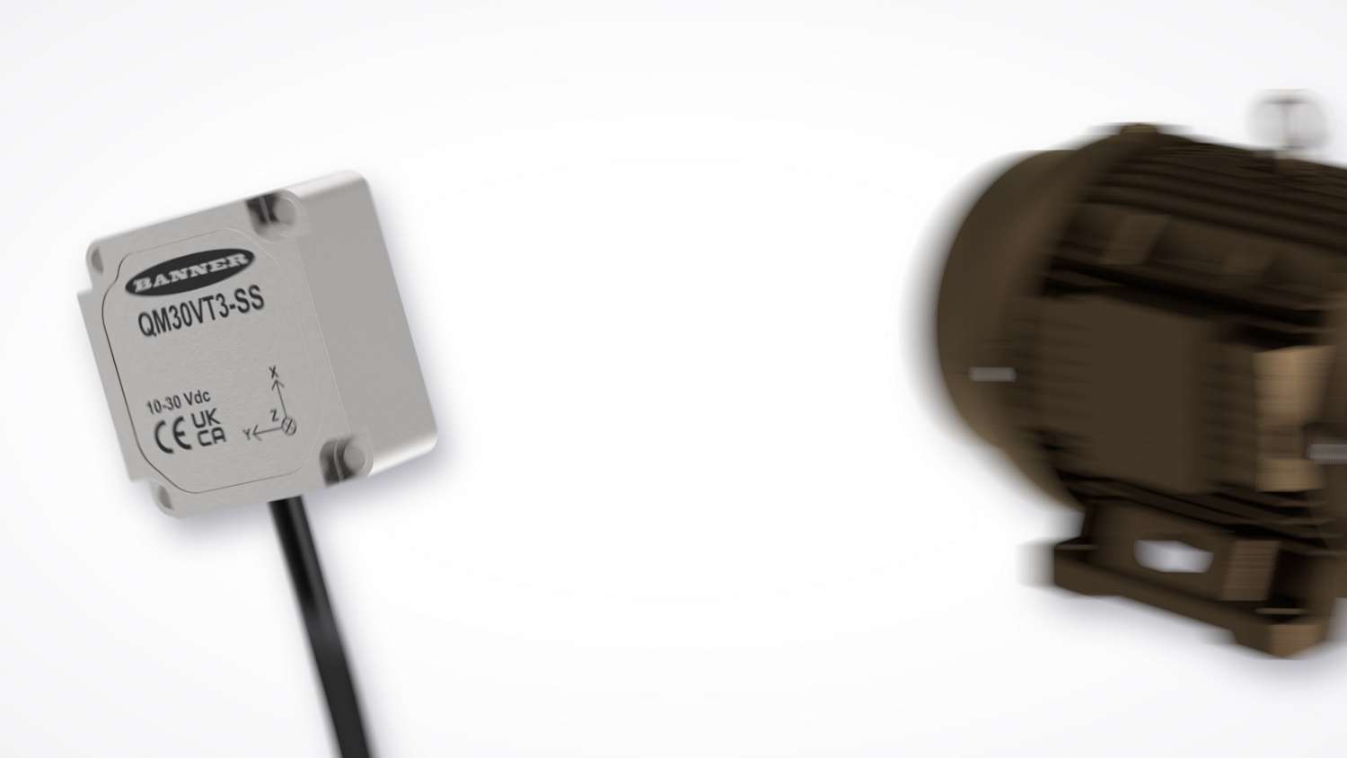
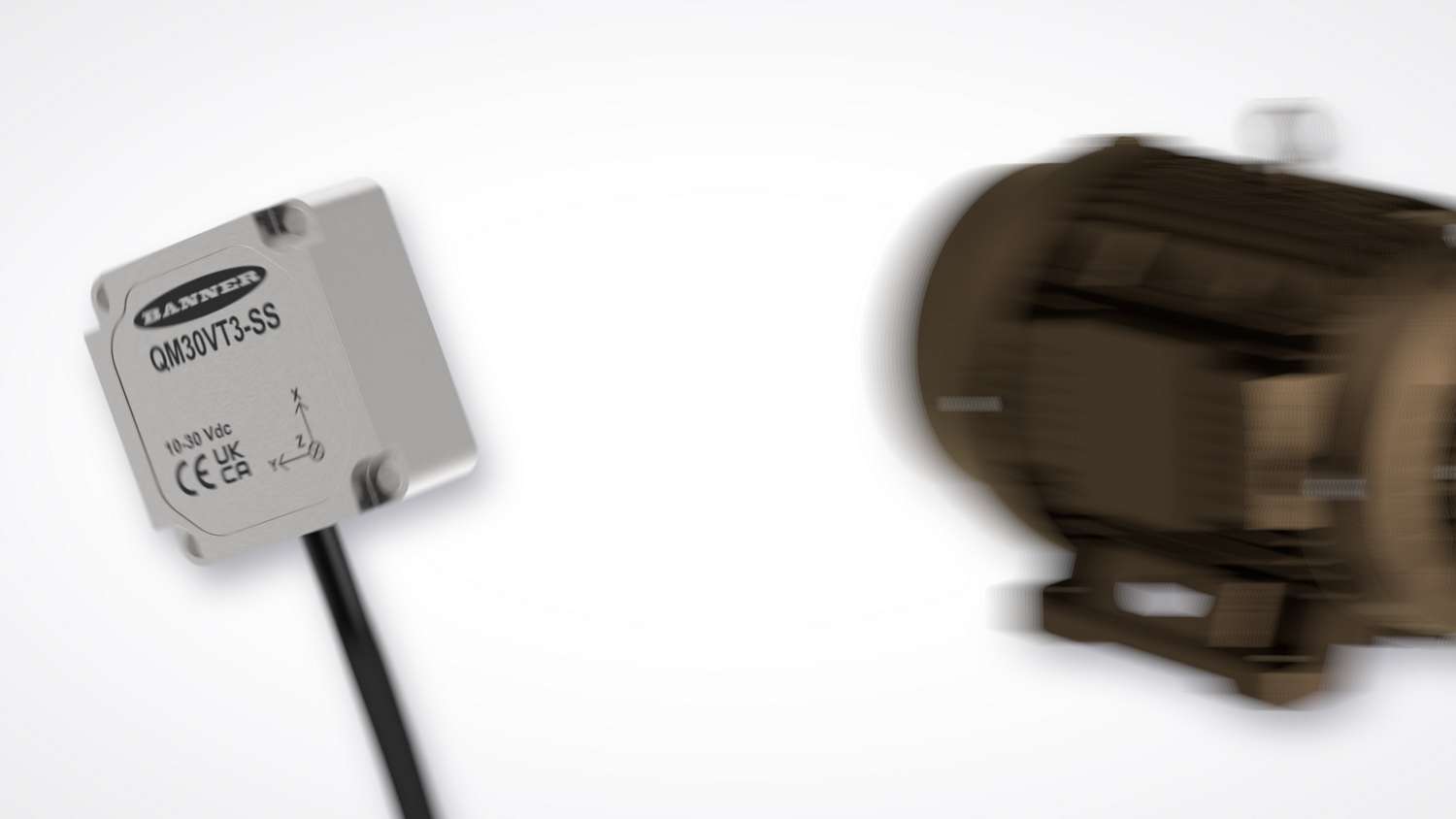
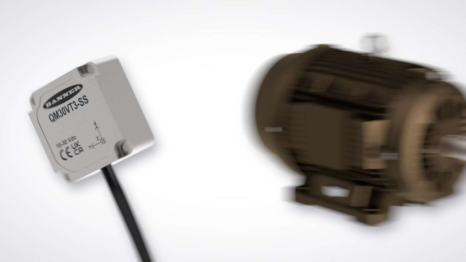
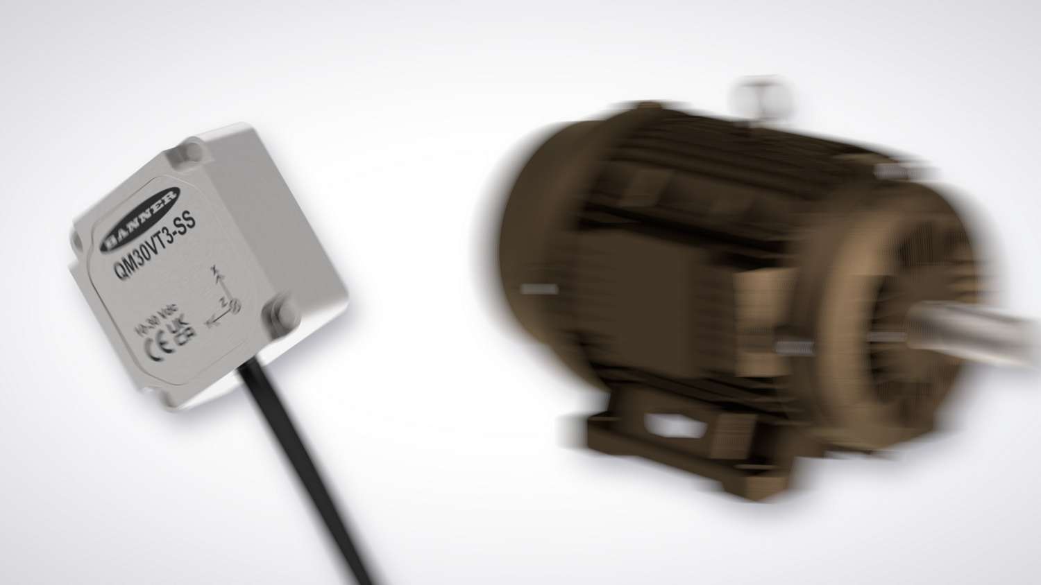
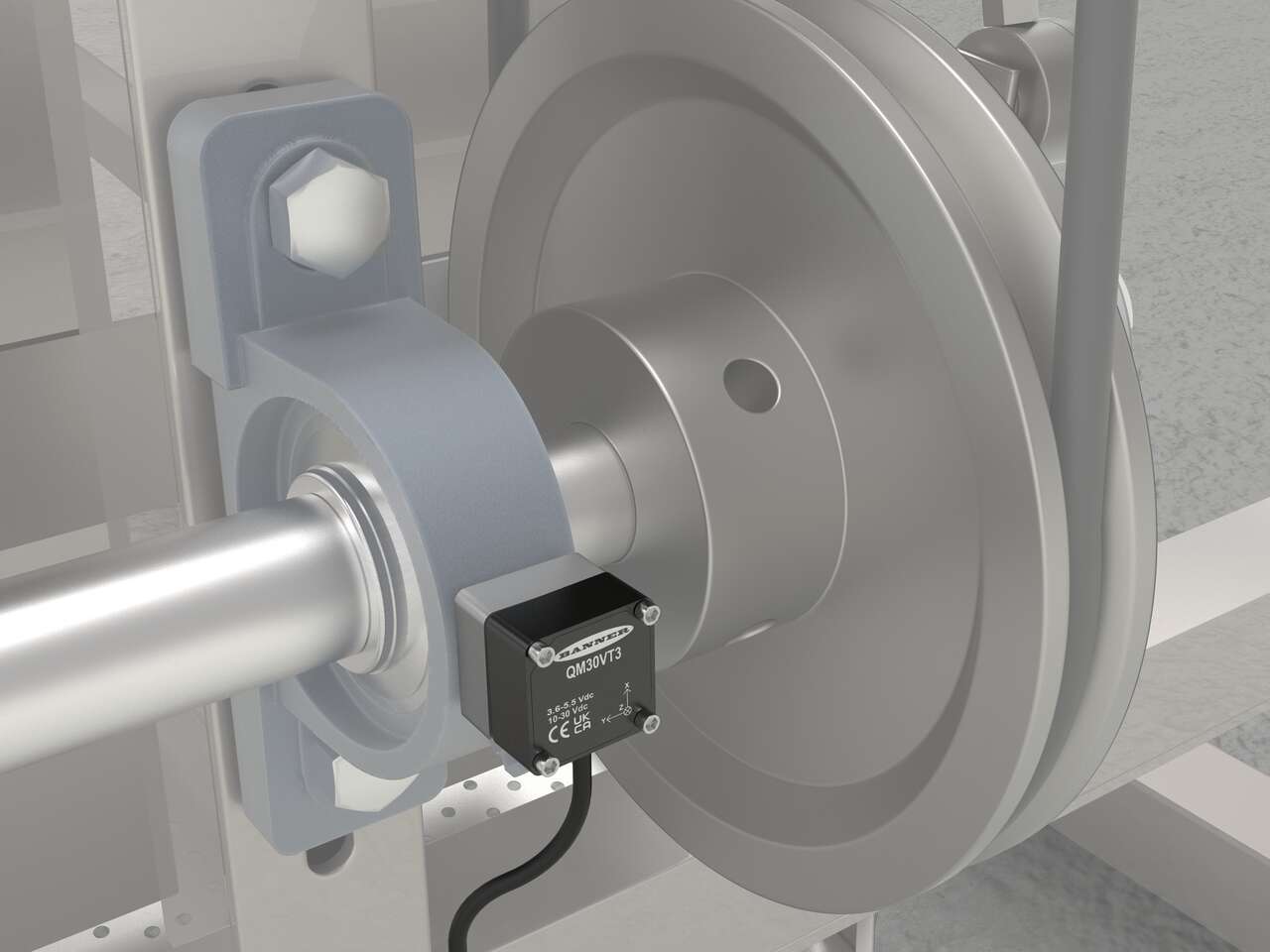
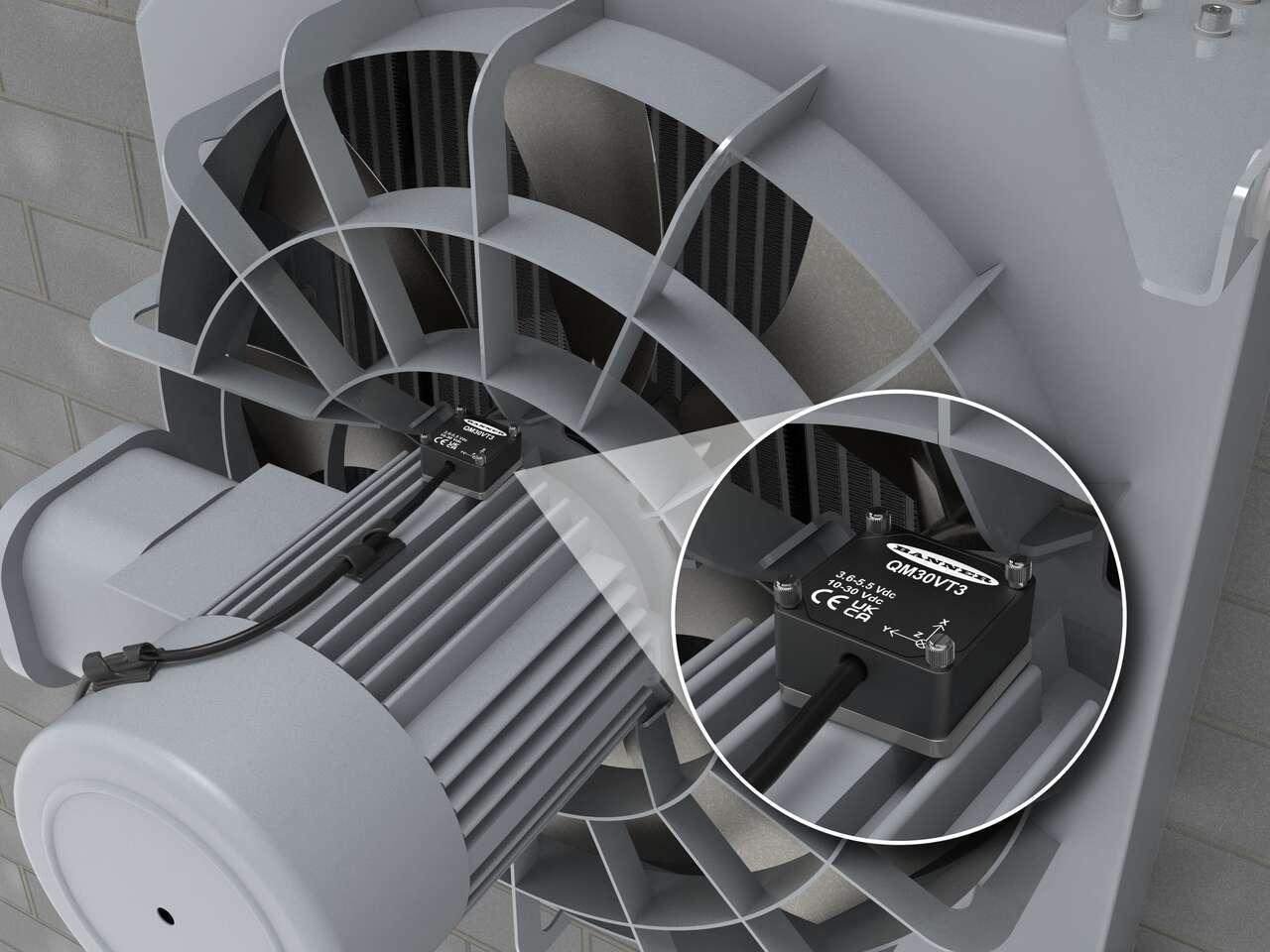
Detect early-stage fault symptoms in motors, gearboxes, and other equipment before failures escalate. From imbalances and misalignment to bearing wear and gear meshing, the 6 Hz to 5.3 kHz frequency range covers both low-speed and high-speed assets.
Capture detailed low-frequency vibration data and short-duration impact events—like early-stage bearing faults—from slow rotating assets using a high-speed 26.8 kHz sample rate for clear resolution of high-frequency transients.
Adjustable Frequency Max (FMax) lets users tailor the frequency range and sample length to machine speed and fault characteristics. Higher FMax captures a broad frequency range, using shorter sample times and default resolution suitable for detecting faults in high-speed assets. Lower FMax values provide progressively finer sample resolution and longer sampling times for detecting faults in very slow-moving assets.
High-Frequency Enveloping mode (HFE) isolates high-frequency signals by filtering out low frequencies, making it easier to detect early-stage faults like bearing wear and lubrication issues. Combining HFE with a lower FMax setting extends sampling time and improves resolution while isolating high frequencies, which is critical for detecting weak high-frequency fault signatures in slow-speed assets otherwise masked by dominant low-frequency vibrations.
At the center of this example is Banner's DXMR90-X1E Industrial Controller, which collects Modbus RTU data from eight QM30VT3 3-Axis Vibration Sensors. Five sensors are connected directly to the controller: four are daisy-chained in series to Port 4, and one is connected to Port 3. An R70 Serial Data Radio is connected to Port 1 and functions as a wireless receiver for the remaining three VT3 sensors, which are located farther away from the controller. Two of those sensors are daisy-chained into a single R70 for transmission, while the third uses its own dedicated R70. These radios transmit wirelessly to the R70 at Port 1, allowing the DXMR90 to access all eight sensors through a combination of wired and wireless connections. The DXMR90 uses its Ethernet interface to output data over EtherNet/IP, Modbus TCP, or PROFINET networks. This enables integration with PLCs, cloud platforms, or SCADA systems for real-time monitoring and long-term asset health tracking.
Applications
Package sort facility uses 3-Axis vibration sensor with VIBE-IQ to detect early-stage conveyor motor faults, reduce downtime, and enable predictive maintenance.
Plant uses Banner QM30VT3 with VIBEIQ to detect bearing wear and pulley misalignment in fans, enabling predictive maintenance and reducing unplanned downtime.
An ultra-low noise third axis enables mounting in any axial orientation without sacrificing accuracy and reliability, which is critical when space or access limits how a sensor can be positioned. Most 3-axis MEMS sensors have up to three times more noise density in their third axis (typically Z), resulting in reduced reliability and less installation flexibility.
A larger frequency bandwidth improves performance by capturing fault signals that narrower-bandwidth sensors cannot detect—especially high-frequency indicators of early bearing and gear damage. For example, expanding from 4000 Hz to 5300 Hz allows detection of subtle, high-frequency impacts that may not appear below 4 kHz. This enables earlier intervention and makes the sensor effective across a broader range of machine speeds and fault types.
The built-in VIBE-IQ algorithm processes data within the sensor itself, eliminating the need for an external controller or software. It automatically sets baseline rhythms and alert thresholds, allowing users to monitor machine health without requiring specialized vibration expertise.
A scalar value is a single number that expresses the magnitude of a measurable property, without any directional component. It tells you how much of something, but not where it’s going—like °F for temperature or km/h for speed. By contrast, a vector has both magnitude and direction—like velocity; for example, 30 m/s to the east. In signal analysis, scalar values are used to simplify complex waveforms into meaningful metrics. RMS returns a scalar representing average amplitude over time, while FFT produces a series of scalar values representing signal amplitude across distinct frequency bands.
RMS (Root Mean Square) is a method, and a resulting scalar value, for calculating the average amplitude of a signal over time. It captures the full contribution of both positive and negative values, which carry amplitude regardless of sign. This contrasts with frequency-domain methods like FFT, which measure how much amplitude is present at each frequency. In signal analysis—whether it’s mechanical vibration, acoustic pressure, or electrical oscillation—RMS gives you a meaningful measure of a signal’s amplitude over time. In the case of sound, RMS is used to calculate values expressed on a dB scale, which relate to perceived loudness. In mechanical systems, RMS reflects how much force, displacement, velocity, or acceleration is being delivered on average—typically expressed in units like millimeters per second (mm/s) or meters per second squared (m/s²), depending on what’s being measured. These values are useful for assessing wear, stress, or overall performance—unlike peak values, which only capture brief extremes.
FFT (Fast Fourier Transform) is a method for analyzing a signal—such as vibration, sound, or voltage—by breaking it down into its frequency components. It transforms a time-based signal into a representation that shows how much energy is present within narrow frequency ranges (i.e., bins). The result is a series of scalar values indicating the amplitude in each frequency interval. FFT is used to analyze all kinds of signals—mechanical vibration, audio, neurological—anywhere insight is found in the frequency domain.
Have a question about this product series? Our application engineers are here to help with expert guidance and support. Send us your inquiry, and we’ll get back to you as soon as possible. We’re here to make sure you get the answers you need.