
Esempi di programmazione e configurazione del DXM
Questi file di configurazione DXM forniscono funzioni di base per il modulo di controllo wireless DXM che consentono all'utente di provare semplici attività, tra cui un file di configurazione base che contiene diversi esempi di funzioni e aspetti operativi del DXM.
-

-

Sample Starter Configuration Files
-

Sample Timers for DXM1X0-BX Models Configuration Files
-

Sample Tank Level Configuration for DXM1X0-BX Models
-
Reading External Devices with Scriptbasic
-

Real Time Clock (RTC) Push Interval
-

Map a Temperature Input to a Current Output
-

Calculating the Heat Index with a Scriptbasic Program
-
Mapping Many Inputs to One Output (DXM)
-

Monitoring Device Health (MH)
-

Using Bit-Packed Radios with a DXM Controller
-

Reading in Power Information
-

Using Modbus Commands to Unlatch an Input
-

Conducting a Site Survey Using IO 15 Commands
-

Using a Vibration Sensor to Determine if an Asset is Running
-

Monitoring Node Health (Performance)
Sample Simple Counter with Reset Configuration Files
Overview
This simple counter functions by following these steps:
- When Universal Input 1 (UI1), Local Register 1 (Cntr 1 Input via UI1) on the DXM150-B2R1 energizes.
- Local Register 4 (Cntr 1 Low Cnt) increments by a count of 1.
- After Local Register 4 (Cntr 1 Low Cnt) reaches 65535, on the next Cntr 1 input, the value resets to 0.
- Local Register 5 (Cntr 1 High Cnt) increments by 1.
- When UI2 on the DXM150-Bx is energized, the values of both Local Registers Cntr 1 High Cnt and Cntr 1 Low Cnt are reset to 0.
If you are resetting the count values of either Local Registers 3 (Cntr1 High Cnt) or 4 (Cntr 1 Low Cnt) using another device, write a 0 to the appropriate Local Register 5 (Cntr 1 H Cnt Reset Action Rule) or 6 (Cntr 1 L Cnt Reset Action Rule) on Slave ID 199.
All local registers are visible on the display to allow for troubleshooting and acknowledgement of inputs being active.
To configure this simple counter:
- Set UI1 on the DXM150-Bx to be counter registers 4908 = 1 (use either the Register view of the DXM Configuration Tool software or the DXM150-B2R1's LCD). Register 4908 enables the counting function on the rising edge of the input signal.
- Monitor the count value using registers 4910 and 4911.
The Universal Inputs (UI) on the DXM150-Bx Wireless Controller start at Register 3 on Slave ID 200 (I/O Board).
The demonstrated functions include:
- Defining local registers to be:
Counter inputs and counter reset inputs
Counter values
- Creating Read and Write Rules to:
Input to Local Registers
Reset the counter value n the DXM150 I/O Base Board
- Implementing Action Rules to reset the counter value to 0 based on either resetting the input or writing to the counter value reset Local Registers
Sample Starter Configuration Files
Overview
The associated XML configuration file can be loaded into a DXM100-Bx Wireless Controller. This configuration file includes examples of several functions and operational aspects of the DXM Wireless Controller. This configuration does not require remote radios.
Sample Timers for DXM1X0-BX Models Configuration Files
Overview
The associated XML sample programs can be loaded into a DXM150-Bx or DXM100-Bx Wireless Controller.
The Sample Timer XML provides an example of a continuously running timer that resets at different time intervals. It does not require remote radios connected to the DXM1x0 to function. The timer is always running. The DXM display LEDs are enabled by universal input 1 on the DXM100 and isolated input 1 for the DXM150. The input is labeled LED Enable. When the LED Enable input is active, LEDs 1, 2, and 3 on the DXM turn on for 5, 10, and 20 seconds respectively as defined by Action Rules. The timer automatically resets at 25 seconds, then LEDs 1, 2, and 3 are again turned on. This ongoing timer can be used for OEE applications, etc.
One-shot Timer XML provides an example of a timer sequence started with the rising edge transition of the Input Trigger. The InputTrigger is universal input 1 on the DXM100 and isolated input 1 for the DXM150.
All timer and input values can be observed via the display of the DXM.
Sample Tank Level Configuration for DXM1X0-BX Models
Overview
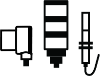
This sample tank level application allows users to set alert ranges using action rules. A K50U Ultrasonic sensor monitors tanklevels. A Wireless TL70 Tower Light uses the red and yellow lights to signal tank levels.
This configuration file starts with a basic monitoring of the battery and incoming power to the DXM100-Bx Wireless Controller. Italso monitors the Universal Inputs of the DXM Controller and the time that it is operating on battery or a power supply.
In addition, the XML is designed to monitor the distance from a K50U ultrasonic sensor connected to the DXM100-Bx WirelessController using a Wireless Q45U Node. The results of the distance measurement are then transferred to a three-color (green,yellow, red) TL70 wireless stack light.
This provides the customer with a method for using a three-color tower light to indicate five statuses. The primary use of theNearing Too Full and Too Full red LED status was to allow the operator time to fill the tank.
Machine operators are more concerned with the Proper Amount (green), Nearing Empty (yellow). and the Empty (red) statuses.Generally, if the green light was not on, they wanted to start filling the tank. If during the tank filing operation the tank wasoverfilled, they also wanted time to take corrective action.
The XML configuration file includes examples of how to use the action rules for monitoring aspects of the DXM100, and there is a schedule set up for emailing stored logs on a weekly basis.
Reading External Devices with Scriptbasic
Overview
This ScriptBasic example reads three registers from an external Modbus temperature/humidity probe connected to the master RS-485 port (pins M+/M-). The external Modbus device is defined as ID 8 in this ScriptBasic program.
See the ScriptBasic manual for more information on the individual functions.
Real Time Clock (RTC) Push Interval
Overview
ScriptBasic can be used to create custom push intervals to a web server. Because the Real Time Clock (RTC) is available to ScriptBasic, ScriptBasic can use the RTC to push data that is aligned to time throughout the day. The program is fairly simple and can be used for any events that need to coincide with wall clock time.
Map a Temperature Input to a Current Output
Overview
Use the programming language ScriptBasic on the DXM Controller to map inputs to outputs of different scales. The ScriptBasic program (NullSpanV2.sb) and associated XML configuration file (NullSpanV2.xml) show an example of how this is accomplished.
When converting between different input/output types, define these four key parameters:
Null
On the input side, Null defines the starting point.
In this example, the Null value is –20 ⁰C (the starting of the output range).
Span
Defines the total range of the input.
In this example, Span is 80. The temperature range starts at –20 °C and therefore ends at +60 ⁰C.
Output Range mA
Defines the total output range. In this example the output is a current (mA) output with a total range of 20000 μA, or 20 mA. For a 4–20 mA output, the range is 16000 μA, or 16 mA.
Output Range mA Offset
If the output range starts at zero, the offset is zero.
For example, 0–20mA. If the range is 4–20mA, the output offset is 4 mA.
Calculating the Heat Index with a Scriptbasic Program
Overview
This example uses a ScriptBasic program to calculate the heat index. These calculations are too complicated to use Action Math Rules but are easily accomplished with ScriptBasic. For more DXM Controller information, refer to the appropriate instruction manual.
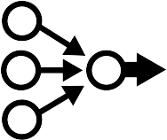
Mapping Many Inputs to One Output (DXM)
Overview
Use the DXM Controller and Action Rules to read multiple inputs, logically OR the values, then write the result to an output or outputs. There are unlimited variations that can be accomplished using Action Rules and Read/Write maps.
This example does not explain how to use the DXM Configuration Tool or discuss details of the DXM Controller configuration.
Monitoring Device Health (MH)
Overview
Monitoring device health is important to do in a network to ensure that all devices are communicating, and all data is up-to-date. This example will cover using a DXM to monitor device health (either MultiHop radios, or Modbus devices) and send an output when a device is no longer communicating as it should.
Using Bit-Packed Radios with a DXM Controller
Overview
This tech note will explain how to use the Bit Packing and Unpacking files with the DXM controller. The required equipment is a DXM700, DXM1000, or DXM1200 controller and up to 47 of P8 or P7 nodes.
P7 and P8 radios are Performance radios that have 12 configurable I/O. They are bit-packed radios, which means that all inputs are packed into a single register for each radio, and all outputs are packed into a separate register. It is possible to mix and match the IO so that you can have any combination of inputs and outputs that add up to 12 (7 in and 5 out, 3 in and 9 out, etc.). The Bit Packing and Unpacking files will unpack the single bit-packed input register into individual registers on the DXM that will just show a simple on/off value (1 or 0). The files will also handle the bit packing to control the outputs on the P7 or P8 radios. This allows the user to simply change a register from a “0” to a “1”, or vice versa, to turn on and off outputs on the P7 and P8 radios.
Lastly, these files are pre-configured to be compatible with ProfNet (up to 47 nodes) and Ethernet/IP (up to 17 nodes).
Reading in Power Information
Overview
Monitoring the incoming power to the DXM IO-Board is a good practice to ensure the power supply for the DXM is supplying sufficient voltage and current, especially if the DXM is powered off a battery (such as a 12 V SLA battery commonly used in solar-powered applications). Note that this is only available on DXM100, DXM150, and DXM1000 models.
From the IO-Board, it is possible to read the following:
- Battery Voltage (mV)
- Battery Charging Current (mA)
- Incoming Supply Voltage (mV, solar or power supply)
- On-Board Thermistor Temperature (°C)
Using Modbus Commands to Unlatch an Input
Overview
Many Banner radios, such as the K70 wireless touch buttons, have a latching input. It can be useful to use Modbus commands so that this input can be cleared without having an operator manually clear the latch by pushing the button a second time. This example will go through reading in the latching input on a K70 wireless touch button and will when a register in the DXM transitions from “0” to “1”.
Conducting a Site Survey Using IO 15 Commands
Overview
Conducting a site survey remotely can be very useful if the DXM is in a location that is hard to reach in person. Using modbus commands, it is possible to conduct a site survey and read the results over serial or ethernet. This example file allows a register to be changed from a “0” to a “1” to conduct a site survey to a performance node. The results from that site survey is then stored in the DXM’s local registers and can be read remotely. Note this file is only intended for use with the performance radios. These files are also setup for Ethernet/IP.
Using a Vibration Sensor to Determine if an Asset is Running
Overview
Using a vibration sensor is a good way to determine if an asset is running or not. When an asset is running, the vibration should be at a much higher level than when it is idle. By monitoring the vibration, and setting a threshold at a certain level, it is possible to determine if the asset is running or not.
The following sensors can be used to monitor vibration:
QM30VT1
QM30VT2
DX80NxQ45VA
Ensure to use a compatible radio with the QM30 sensors. The QM30VT2 may also be wired directly to the DXM.
Monitoring Node Health (Performance)
Overview
Monitoring node health is important to do in a wireless network to ensure that all radios are communicating and providing up-to-date data. This example will cover using a DXM to monitor node health and send an output when a node drops communication.
The health register for performance nodes is always I/O 8 (register 24 for node 1, register 40 for node 2, register 56 for node 3, etc.). The value of this register will be “128” when the node is in normal operation. When the value is NOT 128, then this usually indicates some type of error. The most common error code to appear here is “13569” which indicates a link loss. However, it is usually best (and easiest) to monitor this input and fire an output whenever the value is NOT “128”.
